![]()
Installation and Operation Instructions
We recommend that these Instructions be read fully and carefully before any attempt is made to connect up or use the equipment.
INITIAL CHECK, Check that all valves are firmly seated in their holders and have not become loose in transit, check also that the dial bulb is firmly screwed into its holder. When the amplifier has been supplied in a Teak Case the chassis must first be removed by unscrewing the four 4 BA retaining screws located underneath the case and drawing out the chassis from the back of the case. Before replacing the chassis set the Mains Voltage Adjustment Panel (10) to the correct voltage and check that the Mains Transformer connections located underneath the chassis arc for the correct range, by reference to Diagram No.4. A label will normally be attached to the amplifier indicating which range it has been set for at the factory, but it is wise to double check this as serious damage will result if an amplifier set for 105-140V. range is used on say a 230V. supply. Check also that the Mains Fuse (14) is securely in place and is of the correct rating.
MAINS INPUT. Connect a suitable 3-pin Mains Plug to the 3-core mains lead (12) provided, taking care to see that the GREEN wire is taken to the EARTH pin, RED to 'LIVE' and BLACK to 'NEUTRAL'. (On 105-140V Models 2-core lead supplied).
EARTH SOCKET. Auxiliary equipment which requires to be earthed, e.g. a gramophone motor, should be connected to the Earth Socket (13) located at the rear of the chassis, on no account should earth connections be made direct to the chassis.
AC OUTLETS. For convenience of installation dual A.C. Outlets (15) are provided at the rear of the chassis and may be used to supply gramophone motors, self powered FM Receivers etc. Both sockets are 'LIVE' and are unaffected by the On/OFF toggle switch on the amplifier.
LOUDSPEAKER CONNECTIONS. Connect the loudspeaker leads to the 2-pin plugs provided and insert these in the Impedance Matching Panels (16 and 17) selecting the impedance nearest that of the loudspeaker being used, e.g. a 15 ohm loudspeaker would be used On the 16 ohm position. Note that the LEFT-HAND Loudspeaker should be connected to No. 16 (Channel 'A') and the RIGHT-HAND Loudspeaker to No. 17 (Channel 'B'). If one loudspeaker only is being used initially a 15 ohm 10 watt resistor should be connected across the output channel not in use. The simplest way to do this is to connect the resistor across one of the 2-pin loudspeaker plugs provided and insert the plug in the impedance matching panel as if a loudspeaker were being used.
PHASING. For satisfactory performance it is important that the two loudspeakers should be correctly phased, this may most easily be checked as follows. Place the two loudspeakers fairly close together and playa mono signal through the equipment; standing so as to be an equal distance from the two loudspeakers the sound should appear to come from a point mid-way between the loudspeakers and the source should be clearly defined. If out of phase the source will be indefinite and one pair of speaker leads should be reversed.
Amendment to Installation and Operation Instructions.
LOUDSPEAKER CONNECTIONS
The Loudspeakers should be connected to the four-way
Terminal Block located immediately next to the A.C. Outlet Panel at the
rear of chassis. Small spade shape terminals are provided to facilitate
connection. The impedance to suit the speakers being used is selected
on the Impedance Matching Panels on the Output Transformers by means of
the two shorting links provided. Use the range nearest the impedance of
speaker i.e. a 15 ohm loudspeaker would be used on the 16 ohm range.
If one loudspeaker only is being used initially, a 15 ohm 10 watt resistor
should be inserted across the output channel not in use.
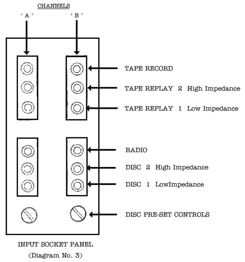
INPUT CONNECTIONS. All Input Sockets are grouped on a single panel
(18) which also includes the pre-set DISC volume controls. Good quality,
lightweight, low capacity screened flex, with an insulated outer covering
must be used for all input connections. The braiding is soldered to the
body of the miniature coaxial plugs provided, the centre conductor to
the' centre pin of the plug.
| Input Socket |
Selector |
Characteristic |
Sensitivity (m/v)* |
Impedance |
| DISC 1 |
Magnetic (M) |
RIAA |
4 |
50-100K |
| DISC 2 |
Magnetic (M) |
" |
80 |
1 megohm |
| DISC 1 |
Crystal (X) |
Flat |
6 |
50-100K |
| DISC 2 |
Crystal (X) |
" |
150 |
1 megohm |
| RADIO |
Radio |
" |
150 |
500K |
| TAPE 1 |
Comp |
CCIR |
4 |
100K |
| TAPE 2 |
Comp |
" |
25 |
500K |
| TAPE 1 |
Flat |
Flat |
25 |
100K |
| TAPE 2 |
Flat |
" |
150 |
500K |
* for 12 watts output
DISC. A separate table gives recommended connections for the most popular Stereo and Mono pick-ups, generally speaking magnetic pick--ups should be used on DISC 1 with the Input Selector at DISC (M) and crystal pick-ups on DISC 2 with the Input ,Selector at DISC (X). When in doubt the advice of the individual pick-up manufacturer should be sought. Pre-set volume controls arc provided on both DISC Inputs and should be adjusted by trial and error so that at normal listening levels the Main Volume Control is at approximately mid-position. With very low output pick-ups it will probably be found necessary to set the pre-set controls to maximum i.e. fully clockwise. Care should be taken to adjust the pre-set controls in step otherwise stereo balance will be affected.
RADIO. Dual radio inputs are provided and may be used for two separate receivers FM and AM or FM and TV or for a Stereo Receiver when this service becomes available. No pre-set volume controls are provided as some form of panel or pre-set control will .normally be found on the average receiver. On our own FM Receivers the variable model has a panel control and the switched model a pre-set control.
TAPE Two pairs of Tape Replay inputs are provided which together with two input Selector positions provide four possible alternatives. The characteristics of Tape Decks and Tape Recorders vary so widely that it has been impossible to draw up a table of recommended connections but generally speaking 'Tape Replay direct from heads, i.e. with a Tape Deck, will be via TAPE l / Selector TAPE Comp. and from the built-in tape replay preamplifier in a complete Tape Recorder via TAPE 2 / Selector TAPE Flat. For Tape Recording duel outputs are available providing 100/250 m/v, according to the input signal and designed to feed into not less than 250K. This output is unaffected by the settings of TONE, FILTER and VOLUME Controls. NOTE: In addition to a Tape Deck a Record Amplifier/Bias Oscillator are essential, these are NOT provided in the HG88 II, but will usually be sold as a Tape Unit. In cases of difficulty the advice of the individual Tape Recorder manufacturer should be sought.
MOUNTING
CASE MODEL.
When supplied in a Teak Case the amplifier is free-standing and may be placed on any convenient table, book-shelf, room divider etc. Great care must be taken to ensure adequate ventilation, the top grille should on no account be obstructed and a reasonable flow of air should be provided around the back of the cabinet, i.e. it should not be placed hard up against a wall.
CHASSIS- MODEL.
When supplied in chassis form, for mounting in a conventional
equipment cabinet, the unit requires a panel opening 5 1/4," x 14 1/4".
A substantial shelf, measuring approximately 16" x 11" should be provided
flush with the bottom edge of the cut-out. To avoid impeding ventilation,
through the louvered base plate of the amplifier, an opening, approximately
12" x 8" should be cut in the shelf. The opening should be positioned
centrally in the shelf. The Front Panel is now fixed in place, by means
of the four 3/8" nuts provided, which are screwed onto the bushes of the
FUNCTION, BALANCE, SELECTOR and VOLUME Controls. The seven control knobs
are now fixed taking care to see that the pointers line up with the markings
on the panel. The amplifier is now placed in the opening from the front
of the cabinet and carefully slid back until the panel escutcheon bears
on the front face of the cabinet. The chassis may now be secured in a
position by means of the four 4 BA screws provided, holes having been
drilled in the shelf to clear the screws and coincide with the hank bushes
on the chassis. If more convenient tile chassis may be retained by the
two rear screws only.
NOTE: We do NOT recommend that the amplifier be mounted so that the front
panel is in a horizontal place, i.e. 'hanging down'. This will seriously
impair ventilation, and cause overheating and subsequent damage.
ROGERS DEVELOPMENTS (Electronics) LTD
"Rodevco Works" 4-14 Barmeston Road
Catford, London S.E.6.
Telephone: Hither Green 7424
CONTROL FACILITIES
SELECTOR.
Five-position Input Selector enables programme source to be selected. DISC X. DISC M. RADIO. TAPE Comp. TAPE Flat.
FUNCTION.
Four-position Function Selector enables mode of operation to be selected. STEREO. MONO A. (Both Amplifiers in parallel from Input Channel A). MONO B. (Both Amplifiers in parallel from Input Channel B). MONO DISC. (Both DISC Input Channels connected in parallel and fed to both amplifiers in parallel - for use when a compatible Stereo pick-up is used to playa Mono record).
BASS and TREBLE.
Continuously variable ganged controls. Optimum settings depend on programme material, room acoustics and personal taste. It is therefore impossible to give recommended settings, a start should be made with both controls set level.
BALANCE.
Permits adjustment of the relative outputs from The
two channels. Initial adjustment may be made as follows: Play a Mono record
with a Stereo pick-up with FUNCTION switch at STEREO. Adjust BALANCE control
until sound appears mid-way between loudspeakers; note setting.
This setting will hold good, except in the case of misbalanced programme
material or possibly if the relative position of the loudspeakers is changed.
VOLUME.
A close tolerance ganged control affecting the overall volume level on both channels. Has no effect On the output from the Tape Record sockets.
ON/OFF SWITCH.
Two-position toggle switch controls mains supply to amplifier In the ON position the amber dial light will be illuminated Switch has no affect on A.C. Outlet sockets which are permanently live.
![]()