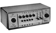
| Fisher 80-C mono preamplifier |
|
WHEN the Fisher Model 50-C "Master Audio Control" was introduced, approximately three years ago, it won immediate public acceptance. Inspired by this public acceptance and the desire to anticipate future high-fidelity trends, a research program was initiated for the development of a new "Master Audio Control." As a result of this program, it was found possible to do the following: improve the signal-to-noise ratio; reduce distortion to a new low; provide more accurate phonograph equalization settings, more effective bass and treble tone control circuits, and a higher degree of ease and flexibility in switching. In addition to improvements in circuitry, it was foreseen that complete mixing facilities should be incorporated as a result of the increased acceptance of tape recorders in the home. Also, with the major record manufacturers producing recorded tapes on a large scale, it became evident that it should be possible to treat this new medium with the same simplicity as one treats the record. That is, preamplification and equalization should be provided so that only a basic tape transport mechanism will be needed to reproduce these tapes. Such a mechanism therefore parallels the role of the record changer in function and in comparably low price. In addition, since an audio control unit will become a decorative element in thousands of homes, it is imperative that it be well styled, so that it will be a welcome addition to living room decor. This article describes the new "Master Audio Control" which, with the aid of a number of new and unique circuits, meets all these requirements. The unit is intended to satisfy the most exacting and complex needs in top-quality home systems, with something to spare. Seven inputs are included, designed to match the needs of every type of signal source which may be used in home systems, as follows: (1) magnetic tape playback head; (2) magnetic pickup; (3) crystal pickup (or any constant-amplitude pickup); (4) low-level microphone; (5) radio tuner; (6) and (7) two high-level auxiliary inputs. Up to five sources can be switched in simultaneously and mixed in any proportion, with the ease and lack of interaction that characterizes the best professional consoles. The pickup inputs are on a "phone" channel. The tape-head input is switched onto the phono channel when the lever switches for record compensation are depressed to a bottom position marked "Tape," which will be discussed later. The phono channel is one of the five mixing channels, any one of which can be mixed with any or all of the others. The other four are the radio, microphone, and two auxiliary channels. The five mixer-level controls are all controlled by knobs on the front panel. Channels are selected by push-buttons which are in a row beneath the mixer- level controls. The operator merely pushes one button or two, or more simultaneously, to connect the channels he wants. A pilot light under each button indicates which are in use at any time. The tuner input and the two auxiliary inputs are fed directly to the first of two pairs of direct-coupled triodes which form the main amplification line of the unit. The microphone input, with an input impedance of 18 Megohms, includes a triode preamplifier which gives enough additional gain so that high-quality dynamic or crystal microphones, with their low signal levels, can be used. The gain of this stage is over 32dB. The two pickup inputs and the tape-head input feed through a separate two-stage amplifier, which incorporates the pickup and tape equalization and the record compensation circuits. These equalization circuits are of the selective feedback type, which not only provides the equalization but also keeps the distortion and noise produced in the two stages at a low level. The gain of this stage, when used on phonograph, is 32dB at 1000 cycles. In the tape position it is 37dB at 1000 cycles.
There are four bass turnover points and four treble roll-off curves, to make 16 different record compensation curves. As shown in Fig. 1, these cover all the presently used recording curves, as well as those of recent years. A fifth position on the two lever switches for the record compensators, as already mentioned, provides the proper gain and equalization for a signal taken directly from a tape playback head. Fig. 2 shows the equalization curve which is in effect in this position of the compensator. This equalizer position and the tape-head input, give the music lover who wants to add tape playback facilities a convenient and economical way to do so. A tape "deck" which includes just the playback head and the transport mechanism—no electronics—will put the buyer "into tape," at a cost for the tape equipment comparable to that of disc playing equipment of similar quality. Tape decks of this description are available on the market at various price levels. If the user, however, already has or prefers to buy a tape machine which includes equalization and preamplification, he can, of course, connect it to his system through one of the high-level auxiliary inputs. Two of the channel selector buttons, those for the radio tuner and for Auxiliary No. 1, each automatically connects the a.c. power to a separate a.c. outlet on the back of the chassis. Thus a radio tuner or other program source which requires a supply of a.c. power will draw power only when it is actually in use, being turned on automatically when the channel button is pushed in. A third a.c. outlet on the back of the chassis is for the power amplifier and supplies power when the master switch of the unit is turned on. A new circuit device eliminates the signal loss which usually occurs in conventional mixing circuits and, together with the resistors in series with each grid, keeps interaction between channels at a negligible level—less than ½dB. This is important in maintaining the high signal-to-noise ratio built into the individual channels. All channels come together at the grid of V2A, the first triode of the first direct-coupled pair. The feedback voltage around this pair comes off a voltage divider consisting of resistor R25, plus the total grid-to-ground resistance in the first triode circuit. Since additional channels, as they are switched in, add the channel resistance in parallel with that already in the circuit, the feedback voltage is reduced for each channel added. This increases the gain of the two tubes to offset the mixing loss. No degradation of quality occurs as channels are mixed in. When a channel is out of the circuit, it is grounded to prevent crosstalk. The signal is taken from the cathode of the second tube in the first common pair to give a low-impedance drive for the following loudness control and tone control circuits. This is another important factor in the remarkable signal-to-noise characteristic of the unit: the low impedance keeps down stray hum pickup and noise in the equalization and switching circuits that follow these controls. The loudness control can be switched in or out from the front panel and is connected to the first section of a dual master volume control. At low settings of the master volume control, with the loudness circuit switched in, there is maximum accentuation of the bass and treble ends of the spectrum, to match the low-volume Fletcher-Munson curve. At high settings of the master volume control, the accentuation is lessened, as shown on the curves of Fig. 3. Thus the amount of loudness compensation at any given loudness can be adjusted to personal taste and to the acoustic character of the room by the relative settings of the mixer level controls and the master volume control. To increase the compensation at any given loudness, it is only necessary to set the master control down and the mixer control up or vice versa.
The tone control circuit is essentially the Baxendall circuit, with modifications to reduce the noise level. This is also a selective-feedback equalization circuit, with the feedback taken from the plate to grid of tube V3B, which functions purely as a tone control tube —there is basically no gain in the stage. The tone control curves are shown on the chart of Fig. 4: they are of the variable-crossover, constant-slope variety, with a maximum boost or cut of 15 decibels at both the bass and treble ends of the spectrum. The tone control knobs have marker dots which show instantly where the "flat" setting is. The use of pairs of triodes with appreciable negative feedback around each pair gives the unit as a whole extremely high stability, with freedom from variation in performance because of normal aging of tubes or other components, or normal shifts in supply voltage. The four feedback loops in the unit also aid in producing the truly vanishing level of the distortion and noise. Harmonic distortion is 0.05% (five hundredths of one per-cent) at an output of five volts, more' than •enough to drive most power amplifiers to full output. Intermodulation distortion is unmeasurable at the same 5 volts output. At 10 volts, IM distortion is 0.2%, and at 15 volts it is 0.65%. The noise level, including hum and all other sources of noise such as tube hiss, is better than 85 decibels below the signal at 2 volts output, on the high level channels. On the phono channels, the noise is 72dB below a 10-mlllivolt input signal. Distortion and noise have, in effect, been "designed out" of this unit. The two output circuits, one for feeding a tape recorder and the other for the main power amplifier connection, are both from cathode followers, allowing the use of long cables without loss of signal quality. The tape recorder output follows the first pair of direct-coupled triodes, so any of the input channels can be mixed to feed it, with a total gain from high-level signal input to tape recorder output jack of 3 decibels. The main cathode-follower output has an exclusive circuit which contributes to the low noise level of the unit. The second half of the master volume control is connected in parallel with the cathode-follower load resistor, that is, the volume control is right across the output cable. This placement of the volume control has been avoided in the past, because (1) a low-resistance control in this position upsets the performance of the cathode-follower tube, producing high distortion; (2) a high resistance control does not bother the tube, but produces a high impedance for the output cable to "look back" at, when ever the control slider is in the mid- range of the resistance. This makes the cable susceptible to hum and noise pickup, and produces loss of high-frequency response in the cable capacity. In the present unit, the control has a comparatively high resistance, but negative feedback is taken from a tap on the control back over the two final stages. This lowers the output impedance for all settings of the control, so that cable noise and loss effects are practically eliminated. It allows the control to be put at the output of the unit, with the advantage that the signal-to-noise ratio is not impaired as the control is turned down. If the control were ahead of one or more stages, the noise produced in those stages would not be reduced as the signal is reduced by the control. With the control across the output; signal and noise are reduced in the same proportion, as the control is turned. The maximum gain from all high level inputs to this output is 21dB. The power supply has two separate rectifier circuits, one for the plate voltage and one for the direct current which is used on the heaters of all tubes. The plate supply is a full-wave circuit using two selenium rectifiers and a four-section resistance-capacitance filter, which practically eliminates plate-supply ripple. The direct current for the tube heaters comes from a selenium bridge rectifier and two-section filter and is another essential factor in the extremely low noise level of the unit. A separate winding on the power transformer supplies all indicator and pilot lights. The specially-designed transformer is completely potted and magnetically shielded with a very low temperature rise which means long life for the various small parts in the unit. Terminal board construction keeps the small parts below the chassis firmly in place. All tubes and associated parts are on a separate rubber-mounted sub-chassis to reduce microphonic effects. The unit is completely shielded, with a metal bottom plate. Arrangement of the, controls on the front panel has been carefully designed for maximum convenience and quick identification. By putting a large knob for the master volume control in a visually-emphasized sub-panel, at the left end, and the tone controls to similar prominence at the other end, it is possible for those members of a family who have no interest in the more complex functions to adjust the unit; undisturbed by "all that stuff in the middle." The symmetry of the arrangement, the outward slope and the brushed—brass finish of the panel, present a modern, clean-cut appearance. It can be seen from the foregoing that the new Fisher 80-C represents a complete and extremely flexible audio centre. G. P. Maerkle, Vice-President
and Chief Engineer, Fisher Radio Corporation |
|||
 Taken
from 'Radio and Television News', November 1955
Taken
from 'Radio and Television News', November 1955
