| Grommes 'Little Jewel' integrated mono amplifier (1953-1958) |
|
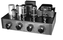
GROMMES Little Jewel amplifiers have been firmly established in the affections of thousands of users for a good many years. Designed without frills or fancy extras of any kind, these amplifiers do a workmanlike, reliable job of giving more listening pleasure per dollar invested than possibly any other item of high-fidelity equipment. Although the basic design has changed very little, there have been minor modifications—particularly in controls and input circuits—through the years. The latest model (LJ-6) costs $39.50 ready to play; as a kit (Model LJ-6K), the price is $24.95. A metal cage cover is available at $4.75; without the cover, the kit appears as shown in Figs. 1, 2, 3, and 4. Rated power output of the LJ-6K is 10 watts at middle frequencies, with 15 watts peak power. There are two high-level inputs (marked AUX-TAPE and RADIO) and a phono input channel with two alternative input circuits (one for a conventional magnetic pickup, the other for a ceramic or other constant amplitude pickup). The selector switch has three positions of phono equalization (FLAT, RIAA, and OLD LP) which are effective on either phono input. A treble control supplies variable high-frequency cut only, and is combined with the AC on-off switch. The bass control (which furnishes variable boost only) is designed to interact with the volume control in such a way that the amount of boost available at any given bass-control setting is dependent on the volume-control position; thus, it acts much like a variable loudness-compensation control. At volume-control settings beyond 6 (approximately 1:00 o'clock position), very little bass boost can be obtained. This is a clever and entirely sensible feature that minimizes the danger of overloading the amplifier, which has limited low-frequency power output.
The LJ-6 circuit (above) is simple and conservative. One 12AX7 is used as a phono preamplifier with feedback equalization. The selector switch couples the preamplifier's output, or one of the high-level inputs, to the volume control, which has the bass tone-control circuit connected to a tap on it. From the volume control the signal goes to a paraphase-circuit inverter, using another 12AX7. This drives a pair of 6V6GT output tubes in standard beam-power connection with cathode bias. Feedback amounting to 12db is brought from the output-transformer secondary to the first inverter section's cathode. All filtering in the power supply is accomplished with resistance and capacitance. Hum reduction is obtained by connecting the filament winding's center tap to the output-stage cathode at a potential of 21 v.
Construction Notes Instructions always emphasize the importance of reading and understanding thoroughly all directions before attempting the construction of any kit. I'd like to second this advice. When I first looked at the four pictorial diagrams supplied I was sure that I would have no trouble, but as I started actual construction I felt the need to study the diagrams more thoroughly. That part of the assembly shown in Figure 1 of the directions presented no difficulties. I found, however, that it was necessary to trim some of the leads about ½ in. in the second step of the wiring in order to make the angles of the leads correspond to those shown in the diagram. Possibly it would have been all right to use the leads as they were supplied, but because this was my first amplifier I wanted to be extra careful. After studying an actual photograph that was included with the directions, I decided that the wisest thing to do was to cut off the ends of the leads where needed. Work on the next group of wiring directions was a bit more confusing. None of the wiring done in the first group is shown in the second, and I found myself glancing back and forth between the two in order to be sure that I was supposed to attach a second wire to a particular lug. figs. 1 and 2 show how the amplifier looked at this point. Anyone who has done much kit assembly would not have experienced the confusion I felt in wondering how much the resistors and capacitors. I decided finally that I would not cut off any ends until the resistor or capacitor was actually ready to be soldered in place. When I came to the final group of wiring directions I was beginning to wonder whether or not there would be room for all the remaining parts. By carefully following the diagram I found that I was able to put all the resistors and capacitors in their proper places without having them conflict with those already there. A final check of the diagram against the actual unit showed that there were several connections that were not soldered and that the diagrams did not indicate that they should be soldered. I was sure that a solid connection was needed at these points and, therefore, I applied solder in each place. The completely wired amplifier is shown in Figs. 3 and 4. I was not certain of the reasons for doing many of the things indicated in the directions, but you can imagine my pleasure when the tubes were inserted, the line cord plugged in, the switch turned on, and each and every tube began to glow. With a little assistance the record changer on my radio-phonograph was adapted to make use of the amplifier. What a thrill when I heard the first record played with the amplifier that I had actually built with my own hands! Test Results
The lower part of Fig. 7 shows the action of the treble control, which accomplishes only treble reduction, not boost. Note that the amplifier's frequency response is flat within ± 1 db from 30 to 20,000 cps when the tone controls are set to the indicated flat positions and the volume control is at maximum. The treble-control curves have a tendency to level off at upper frequencies, providing more of a balance adjustment than a continuous roll-off. Maximum continuous undistorted power at various frequencies (as measured by eye on an oscilloscope) is plotted in the upper part of Fig. 7. The curve falls off rapidly below 50 cps; it could hardly be expected to do otherwise in an amplifier of this price. Below 1,000 cps all the curves are much alike, and only moderately accurate; note, however, that well over 20 db boost is provided at 40 cps. Above 1,000 cps both the RIAA and Flat curves are just about perfectly accurate, and the Old LP curve is off only 11/2 db at 10 Kc. Also in Fig. 8 is shown the effect of volume-control setting on high frequency response. As usual, the response suffers most when the setting is for 6 db attenuation at middle frequencies; then it is down (relative to 1 Kc) 3.2 db at 10 Kc, and 7.4 db at 20 Kc. At most settings this effect is barely audible, and can be minimized by keeping the control at or below the 12:00 o'clock position, or near maximum setting. Intermodulation distortion vs. power output of the LJ-6K is plotted in Fig. 9. IM is very low at low operating levels, not reaching the 1% mark until more than a watt. It climbs in almost linear fashion up to 3% at 6 watts, decreases to 2.2% at 9 watts, and doesn't reach 3% again except at powers above 10 watts Test frequencies were 60 and 7,000 cps mixed in the standard 4:1 ratio. If a higher bass frequency had been chosen, the IM figures would have been substantially lower up to the break point. This points up the standard weakness of very low-priced amplifiers: the output transformer, which limits the low-frequency power-handling ability. The LJ-6K is not, however, weak in another area in which low-priced amplifiers often suffer, and which may be more important to listening quality: stability. Its low-frequency stability is excellent, and at high frequencies it is very good also. It refused to oscillate or even peak badly with any value of capacitance across a resistive load. We measured the amplifier's sensitivity at 1 Kc as the input required to produce clipping of the output wave form. On the phono input, this was 4.4 mV; on high-level inputs, 0.74 v. Noise was 35.5 db below maximum output on the RIAA position of the selector switch, and better than 80 db down in the RADIO and TAPE-AUX positions. The noise and hum level was affected quite substantially, incidentally, by the orientation of the line plug in the wall socket. We found that the noise, on a practical listening basis, was insignificant with any but very low-level pickup cartridges. The sound was very listenable, even with speaker
systems of fairly low efficiency, if sound levels were kept reason- ably
moderate. Within its limitations the LJ-6K is a good, dependable amplifier,
with flexibility unique (so far as we know) at its price. No one need
hesitate to use it as the basis for a modest hi-fi system. |
|||
 Taken
from Audiocraft Magazine, August 1958
Taken
from Audiocraft Magazine, August 1958
 Everything
is supplied in the LJ-6K, even to 38 individual pieces of hook-up wire
cut to size and with the ends trimmed. All you need to assemble this one
is a screw driver, pliers, soldering iron, and solder. We assigned the
kit to a young lady in our advertising department, who prepared the notes
in the following section.
Everything
is supplied in the LJ-6K, even to 38 individual pieces of hook-up wire
cut to size and with the ends trimmed. All you need to assemble this one
is a screw driver, pliers, soldering iron, and solder. We assigned the
kit to a young lady in our advertising department, who prepared the notes
in the following section. Fig.
6 represents the action of the bass boost control as interrelated with
the volume control. Solid lines are response curves obtained with the
volume control turned an eighth up from its minimum position; the lower
solid line, with a maximum of nearly 11 db boost at about 80 cps, is for
the bass control turned halfway up; and the upper solid line, with a maximum
of 16 db boost at about 45 cps, is for the bass control fully up. Dot-dash
and dash lines are for similar bass-control settings at ¼ and ½
rotation of the volume control, respectively. It can be seen that turning
down the volume control increases bass boost for any given setting of
the bass control. At volume-control positions beyond about two-thirds
of the way up from minimum, it is impossible to obtain any significant
bass boost no matter how the bass control is adjusted. In addition to
reducing the possibility of overloading the amplifier, this action provides
for a flexible sort of automatic loudness compensation without the expense
and complexity of an extra loudness control. The bass control does not
furnish bass cut, however.
Fig.
6 represents the action of the bass boost control as interrelated with
the volume control. Solid lines are response curves obtained with the
volume control turned an eighth up from its minimum position; the lower
solid line, with a maximum of nearly 11 db boost at about 80 cps, is for
the bass control turned halfway up; and the upper solid line, with a maximum
of 16 db boost at about 45 cps, is for the bass control fully up. Dot-dash
and dash lines are for similar bass-control settings at ¼ and ½
rotation of the volume control, respectively. It can be seen that turning
down the volume control increases bass boost for any given setting of
the bass control. At volume-control positions beyond about two-thirds
of the way up from minimum, it is impossible to obtain any significant
bass boost no matter how the bass control is adjusted. In addition to
reducing the possibility of overloading the amplifier, this action provides
for a flexible sort of automatic loudness compensation without the expense
and complexity of an extra loudness control. The bass control does not
furnish bass cut, however.