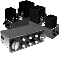
| Kerr CWA10 power amplifier and DS1 stereo control unit (1962) |
A report on an item designed and made in Scotland is not a frequent occurrence. To be sure, there has for many years been large scale manufacture, in fact, a production galore, of a high fidelity product, distortion free, of excellent long term stability and high damping factor: but that is more in the province of the founder of THE GRAMOPHONE and mine must be a drier report, though I hope only in the physical sense. Mr. Kerr brought a prototype of this new amplifier to Oxford, breaking his return journey from the Audio Fair. It was unusual in design and conception for he said that whenever a decision had to be made in the course of development the arbiter was always the ear. Certainly, when we quickly hooked it up it was apparent that here was the clean, easy sound which we expect from top-line equipment. Some weeks later, as the design was settled, a model arrived for test and since then the final modifications have been incorporated, and I can now give the results of detailed tests and describe the layout and appearance. For a change let me start by describing the power amplifiers. From the specification it can be seen that these boast a very wide frequency range; and at this the experienced reviewer always looks for an excessive amount of negative feedback with consequent stability problems and poor overload characteristic. This experienced reviewer was caught: in fact, the overall feedback is modest (18 dB) and the wide response is due to an excellent output transformer, a circuit which has multiple feedback paths inside the main loop, and an absolute minimum of reactive components. Only three capacitors appear in the amplifier proper (six more are in the power supply section) two are coupling capacitors to the output valves and the other a phase advance across the feedback resistor. The output valves are EL84 pentodes in the ultra-linear circuit arrangement and they are biased from a separate negative voltage source, rectified and smoothed from a tap on the mains transformer. A normal valve rectifier and resistor/capacitor smoothing is used on the HT supply. An ECC81 double triode valve as input stage, directly coupled to a divided load phase-splitter completes the line up. The physical size of the amplifier does not suggest its capabilities although the dominant power and output transformers are not to be denied. A deeper than usual chassis of heavy gauge aluminium, corner welded, anodized and lacquered, houses almost all the small components on a single vertical tag board. First class materials are used throughout, from the heavy duty Belling Lee terminals for loudspeaker connections to the high stability low noise grid resistor. An octal socket is provided to take off spare power and a mains outlet is available. On test I could not quite achieve the result claimed in the specification, but only in one quite unimportant detail - the power available at supersonic frequencies. In both my models this fell to 8 watts at 30 kc/s. Otherwise all was more than satisfactory. Although my test gear doesn't measure accurately down to 2 c/s the response was good down to 10 c/s and below this I don't think many people will care. There was a trace of instability under certain conditions, but reference to Mr. Kerr provided a speedy cure (now incorporated) and this side of things is now well above average - an important point with the growing use of electrostatic and ribbon loudspeakers. Turning to the DS1 stereo pre-amplifier, the striking appearance is the first thing to call for comment and description. Perspex is the material used for both fascia and knobs. The former, reverse rear printed with the necessary indications and backed by a grey coloured material, is edge illuminated by a pilot lamp concealed behind the circular nameplate. It is separated from the metal chassis by a wooden spacer. Normal mounting is through a cut-out (template provided) and a 'U' clamp wing-nutted from the rear. An alternative is to remove the Perspex panel, take off the wooden distance piece for use as a template to drill clearance shaft holes in the cabinet and then to fit the Perspex back over the wood of the cabinet omitting the background material. This second method although perhaps more difficult is most attractive if a suitably figured panel exists, for the small white knobs and the two larger gilt ones, together with the lettering, appear to be floating on the surface of the wood. In essence, the DS1 is two separate mono control units built back to back on each side of a dividing metal shield. There are separate bass and treble controls for each channel and the volume control knob is in fact a concentric pair of identically sized knobs so close together that they can easily be gripped and turned as one if required. The independent control thus provided removes the need for a balance control and at the same time can be accurately set. The rear knob has a gilt rear surface with a circular clear window through which the setting numbers one to eight are visible. A clear knob is used as the front control marked with a single dot which is centred over the circle of the rear knob in the balanced condition. I normally dislike these arrangements of two knobs to do one job, but in this case with these easily handled controls of two and a quarter inch diameter there is no real disadvantage. Similarly, I do not wish to have independent tone controls for each channel. To quote from the excellent instruction manual: "Separate Bass and Treble Controls are provided for each channel. This can be of considerable value in balancing dissimilar loudspeakers. It also enables pseudo-stereophonic effects to be obtained from monaural programme sources". This is true but all tone controls change the phase of sounds of differing frequency and thus alter the stereo image if applied dissimilarly and such use can only be a makeshift. Fortunately we don't use tone controls so frequently these days so this doubling of their number may be largely ignored. Three controls remain: the other large one is the input selector with the position indicated through the clear window - not so handy until one is used to it for the position of other inputs is not visible and they have to be searched for. The two smaller knobs are mode selector and tone control cut-out switch. The circuit path through each channel is unusual and involves five triode valves, all identical. The first two triodes are only concerned with pure amplification of the low level signals from pickups (mono and stereo), microphone or tape head; there is no equalisation in these two stages. The feature which we have previously noted in the Radford control units is intended to produce a superior signal to noise performance. Any required equalisation can be provided by plug-in networks of a passive nature which are brought in as needed by the selector switch in conjunction with a shaping circuit in the cathode of the following stage. As supplied, these networks gave RIAA compensation on pickup and CCIR on tape. At this point the high level inputs, Radio and Auxiliary, are selected and then a further triode amplifier feeds the fourth as a cathode follower. At its output is a tape record jack, the mode selector switching and the tone control cancelling switch. In the flat position of the latter the signal is passed straight from the cathode followers to the power amplifiers. In the tone control position it goes via passive bass and treble networks to a final triode stage arranged to make good the gain lost thereby and thence to the power amplifiers. The philosophy has been that each signal should only pass through the minimum number of stages required for its adequate amplification and control, all others being switched out of circuit. The five double triode valves needed for both channels all project from the rear of the unit and are thus completely accessible. This is of value as I was able to reduce a slight hum on one channel by 9 dB by changing valve positions notwithstanding that the offender registered 'good' in a valve tester. Most small components are arranged on a long single tag board (one each side of the shield) and all are of good quality. Metalwork and all workmanship would seem to be first class. The test results are summarised below and show that this newcomer from north of the border is fully capable of making the running with other thoroughbreds. Its designers' aim to produce equipment which satisfies the ear even when handling the most complex waveforms seems to have been eminently successful - though my own ear would still occasionally like to have access to a variable slope low pass filter which is quoted as unnecessary! Let us hope that improvements at the source will soon make it so, for if you have an eye for the unusual and an ear for the excellent this could well be the equipment for you. CWA10 POWER AMPLIFIER
GEOFFREY HORN. |
||||||||||||||||||||||||||||||
 Taken
from The Gramphone, October 1962
Taken
from The Gramphone, October 1962