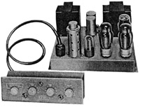
| Leak TL 10 mono power amplifier and 'Point One' control unit |
|
OFFERING MANY of the advantages of the earlier TL/12 amplifier, the new Leak TL/10 brings quality in reproduction to the lower-priced field, yet retains many of the features which made its bigger brother a favourite with British users for both home and professional uses. Direct comparison between the two amplifiers will show that the TL/10 uses continuously variable tone controls instead of tap switches, that it does not incorporate the Vari-slope feature—a low-pass filter with controllable rate of cut-off—and that it uses KT-61's in place of the larger KT-66's. From the standpoint of performance, however, there is not a great difference: the TL/10 has an output of 10 watts at 2.5 per cent IM distortion whereas the TL/12 has an output of about 14 watts at the same distortion figure. The TL/10 has obviously been designed with the American market in mind, for while the TL/12 had the typically gentle tone-control curves usually found in British-made amplifiers, the ranges in the TL/10 are more in keeping with American demands. One feature of the new amplifier is the addition of two jacks on the front panel of the control unit to permit connecting a tape recorder into the circuit with a minimum of effort, and with the assurance that performance will not be affected.
All inputs pass through both of the stages in the control unit—both tubes being EF86's, which are essentially the same as the Z-729 previously reported in these pages (See "Preamp with Presence," Jan. 1954). Frequency-selective feedback around the first stage provides the equalization necessary for phonograph reproduction, and four curves are available—AES, COL-LP, NARTB, and ffrr-78—as shown in the upper section of Fig. 1. A two-terminal strip on the rear allows for the addition of another resistor to permit matching any usual type of phonograph pickup. Flat feedback is used for the tape and tuner inputs, which are also fed to the first stage grid. Response at these inputs is within ±0.5 db from 20 to 20,000 cps. The tone control circuit is essentially the same as the Baxendall arrangement, and provides boost at the frequency extremes before beginning to affect the ranges adjacent to the inflection points. In effect, the response at intermediate settings of the controls may be approximated by sliding the shaded areas of the curves in the centre section of Fig. 1 to the right or left. In usual American practice, movement of the tone controls affects the response adjacent to the inflection points to some degree with even the slightest change, a practice which gives rise to some "tubbiness" in speech because there is considerable boost at 200 cps, for example, when boost at the lower lows is required. The same effect obtains in the high frequencies, and often gives too much boost at the middle highs when only the upper highs are in need of correction. Figure 3 shows the schematic for the control unit, and it will be noted that the output signal available at the tape recorder jack is not affected by the volume control. Thus it is possible to adjust the volume in the monitor loudspeaker at will or to turn it off altogether without affecting the signal fed to the recorder. Tone control adjustments, however, do affect the signal being fed out, which is desirable because it is often advisable to make frequency correction to programs being recorded. A socket is provided to permit feeding plate and heater power to an external tuner which may not have its own supply. The power amplifier follows quite closely the design of the TL/12, but uses KT-61's which are similar to the American 6V6, although somewhat more linear and having greater power sensitivity. The first stage is a pentode, with feedback from the output transformer secondary fed to the cathode. The second stage is the phase splitter, using the "long-tailed pair" circuit arrangement. The output stage is connected in the Ultra-Linear manner, and 8- and 16-ohm outputs are available; 4-ohm speakers can be accommodated by making a simple change on the transformer terminal panel. Four other changes can be made to permit the use of 61-6's or KT-66's, but no particular advantage is offered in using the larger tubes with the supply voltages available. The amplifier is fused, and a receptacle is provided for phonograph motor connection. The complete schematic is shown in Fig. 4. The TL/10 is neat and compact, and is easy to install. As usual in Leak amplifiers, the workmanship is impeccable—a feature which may only be appreciated in case any component ever has to be replaced. But if amplifiers were installed so that everyone could see under the chassis, many more of them would be built like the Leak products. One-watt output from the power amplifier is obtained at full volume-control setting from an input of .017 volts at the tuner and tape inputs, and from .0027 volts at the phono input. At full volume-control setting, hum and noise is 46 db below 1 watt from phono input, and with the volume control off, maximum hum and noise is 72 db below 1 watt. These figures correspond to 56 and 82 db respectively below full output—as most amplifiers are rated to give a higher numerical value. However, a 50-watt amplifier will usually not be played in the home any louder than a 10-watt amplifier, so a figure related to some fixed value of power output is more indicative of actual performance. |
|||
 Taken
from AUDIO, July 1954
Taken
from AUDIO, July 1954 Circuit
Description
Circuit
Description 