| Knight KB-85 stereo power amplifier |
|
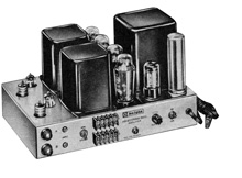
AT A GLANCE: The Knight KB-85, offered by Allied Radio, is a dual-channel basic or power amplifier capable of delivering up to 35 watts per channel with low distortion. Available only in kit form, the unit was built and tested at United States Testing Company, Inc. Dimensions are 14 inches wide, 8½ inches high, and 9 inches deep. Price: $69.95. An optional metal cover costs $6.50. Manufacturer: Allied Radio Corp., 100 N. Western Ave., Chicago 80, 111. IN DETAIL: Inasmuch as each channel of the KB-85 is driven from a level control at the amplifier's input, it is possible to regulate the gain of the amplifier and thereby adjust its sensitivity as required for use with different signal sources. When used as a monophonic amplifier, the "A" channel control becomes the signal level control and the "B" channel control serves to balance the gain of each half of the amplifier. A special balance circuit with a "press-to-test" button is included to help balance the gain for mono use. The amplifier uses two EL37 pentodes per channel in the push-pull output sections, and the output transformers have taps for 4-, 8-, 16-, and 32-ohm speakers. Negative feedback is used from the secondary of each output transformer back to the cathode of the first voltage amplifier. Provisions have been made for balancing the output tubes (provided that a 100-ma DC milliammeter is available). Four meter jacks on the rear panel of the amplifier allow insertion of the meter into the cathode circuit of any of the four EL37 tubes.
This, in fact, proved to be the case in USTC's tests. The KB-85 delivered 33.6 watts of power at clipping with only 0.22% harmonic distortion when only the left channel was operating. With both channels operating together, the left channel provided 30.5 watts of power output at the same distortion level, which is quite good. The right channel operating alone provided 34 watts output at clipping with only 0.27% distortion. The amplifier's power bandwidth, which was measured at the 0.5% distortion level, extended from 27 cps to 16 kc, with the amplifier providing 35 watts output at 1,000 cps. The distortion curve at full power, measured with 33.6 watts output on the left channel, shows that the distortion remains under 1% from 38 cps to 12 kc, but rises very rapidly below and above that range. At half power, however, the distortion remained under 0.5% from 28 cps to 20 kc. The amplifier's frequency response was flat within +0 and -0.5 db from 5 cps to 15 kc. It was down to -1 db at 23 kc, and to -3 db at 48 kc. The response fell off to -9 db at 100 kc but peaked up to +1.2 db at 140 kc, above which frequency it fell off very rapidly again. Square-wave response was very good at low frequencies, showing a relatively small phase shift at 50 cps. At high frequencies, a considerable amount of ringing was observed which is shown in the 10-kc square-wave photograph. Despite this ringing, however, the amplifier was found to be quite stable, even with pure capacitive loading. The intermodulation distortion of the KB-85 was very low, being less than 0.2% up to 10 watts and less than 0.5% up to 33 watts. Total hum and noise was 95 db below full output and the amplifier's sensitivity for full output was 0.58 volts on the left channel and 0.49 volts on the right channel. The damping factor was 16 at the 8-ohm output taps. These are all very favourable figures.
The physical layout of this unit gives a very neat appearance, both from the outside and on the inside, within the chassis. Printed circuit boards are used to make the construction of this unit fairly easy. However, once the boards are installed within the chassis, and are connected in place, only the copper side of the boards is accessible. Additional wiring and components are then placed on top of the boards. Thus, if ever one of the components on the board needs servicing, all this must be removed to get at it, a chore that USTC figures would entail several hours of work for the repairman. Yet, USTC also points out that if the KB-85 is assembled and wired carefully by the kit builder, it may never require such servicing. How It Went Together The kit went together moderately easily for an experienced kit builder who was able to overcome the difficulties encountered. The tube sockets were larger than the chassis holes, and the spacers provided as stand-offs for the printed circuit boards were loo long to permit the application of lock washers and nuts. Accordingly, the tube sockets were ground to fit, and double-nuts were used as board stand-offs. Two capacitors of correct value but different part numbers were supplied without amendment to the instructions or parts list. The fuse was missing and was obtained locally. The components were well packaged for shipment and the plan used by Knight of mounting the resistors on cards simplified their identification during assembly. The instruction manual was in general
carefully prepared, and instructions were simple and concise. Two
minor errors were noted: the reference to "Figure 10 on page
7" should be changed to page 3, and the reference to "Figure
29 on page 25" should be changed to page 21. Total assembly
time was fourteen hours. |
|||
 Taken
from High Fidelity magazine, May 1963
Taken
from High Fidelity magazine, May 1963 The
power supply of the KB-85 utilizes two GZ34/ 5AR4 rectifier tubes
which, combined with a rather hefty power transformer, give the
other tubes all the power they need. The entire power supply is
a very heavy-duty unit, indicating that the amplifier's performance
with two channels operating should be just about as good as when
only one channel is operating.
The
power supply of the KB-85 utilizes two GZ34/ 5AR4 rectifier tubes
which, combined with a rather hefty power transformer, give the
other tubes all the power they need. The entire power supply is
a very heavy-duty unit, indicating that the amplifier's performance
with two channels operating should be just about as good as when
only one channel is operating. 