Babani American Valve
Substitution Information
Before any valve substitution is attempted, the careful reading of the
following explanatory information on the subject is essential.

The substitutions shown in this chart are successful in practically all
cases. There conceivably could be a few instances where circuit
sensitivity to slight differences in valve characteristics might prevent
wholly satisfactory operation, or where the substitute valve type may
have shorter life than the original even though operation is
satisfactory. It is impossible, however, to cover all the exceptions
because of the many deviations in circuit design.

Cross reference in the chart will be found quite complete but not always
reversible. For example, detector diodes such as type 6H6GT should not be
substituted for power diodes such as 6X5GT since the substitute would be
extremely short-lived in this application.

In most cases types of the 6-volt series have identical counterparts in
the 12-volt series, the only difference being in heater voltage. As
examples: except for heater ratings a 6SK7GT is the same as a 12SK7GT;
and a 7A7 Is the same as a 14a7. Rare exceptions to this rule to be noted
are:-
        a 6B8 is similar to a 12C8, not a 12B8;
        a 6a7 is not similar to a 12A7.

                        *       *       *

Where series connection of heaters is used, care must be taken to ensure
the correct amount of current through each heater when the substitute
has a different heater current than the original. If the current is too
high, valve life will be shortened. If the current is too low, operation
may not be satisfactory. Compensating resistors therefore must be added
to adjust the current. The following two examples will assist in
calculating these resistors:-

1. To replace a 150-milliampere valve, such as a 7B7, with a 3OO-
milliampere valve, such as a 7A7: The series heaters of the original
valves of the receiver have a normal current of 150 milliamperes. Since
the substitute type operates at 300 milliamperes, shunt resistors must be
connected across each of the other valves. The value of each resistor
must be equal to the heater resistance of the valve to which it is
connected, i.e., the heater resistance of any valve = Heater Voltage
divided by Heater Current.

No resistor should be connected across the substitute valve. In addition,
a ballast valve or resistor cord, when used in the receiver, must be
replaced by a unit having half the resistance of the original.
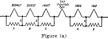
Leads marked X in Figure (a) may be eliminated if care is observed that
these are the only leads eliminated. This means that resistors A, B and
C can be replaced with a single resistor equal to the sum of A, B and C.
The same is true of resistors D and E.

                        *       *       *

2. To replace a 300-mllliampere valve, such as a 7A7, with a 150-
milliampere valve, such as a 7B7: The series heaters of the original
valves in the set have a current of 300 milliamperes. Since the
substitute valve operates at 150 milliamperes, a shunt resistor equal in
value to the resistance of the valve must be connected across it. The
heater resistance of the 7B7 valve is equal to Heater Voltage divided by
Heater Current; so 6.3 / 0.15 = 42 ohms.

See Figure (b).
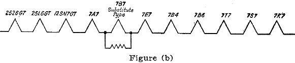
The parallel combination will then pass twice the current of the valve,
so that 150 milliamperes flow through the valve and 150 milliamperes
through the 42-ohm shunting resistor. The current, flowing through the
other valves, will then be the same as in the original circuit.

                        *       *       *

There are a number of cases where remote cutoff and sharp cutoff valves
may be interchanged. ln some cases this may cause slight differences in
the operation of the automatic volume control of the receiver. Metal,
"G," "GT" and "GT/G" types are all directiy interchangeable, although
occcasionally a valve shield may be necessary to prevent oscillation.
Space limitations may prevent the use of the "G" types in certain
installations.

                        *       *       *

An adapter is strongly recommended in place of changing or reconnecting
the socket. The use of the adapter permits the installation of the
original valve type at a later date and avoids confusion in the use of
published circuits for subsequent servicing. However, there will be some
cases where necessary room for an adapter is not-available, thereby
requiring a change of the socket.

Many commercial adapters for substitute types are readily available, but
an adapter can be easily assembled by the serviceman to meet his own
requirements. The following suggestions on adapter construction may be
helpful:-

The use of a bakelite socket which fits snugly inside the top rim of the
base makes a neater and more rugged wiring job. Number 20 tinned wire is
ideal for connecting the top socket to the adapter base. Cut the leads
about an inch longer than necessary, insulate with spaghetti to prevent
short circuits, and pull leads taut when assembled. Cut leads flush with
the end of the base pin, apply soldering flux and, holding the adapter
upright, dip end of pin in a puddle of solder. A small hole drilled in
the soldering iron tip will serve as a solder cup. Solder will flow up
the pin, making a smooth, finished end. Where a top cap lead must be
added, it should be shielded to avoid pick-up troubles.

The base diagrams of the original and substitute valve types should be
used as a guide for the connection between the upper socket and the base
adapter. Three examples are listed below to show the type of
interconnection required:-

(1) 6SA7GT replacing a 7Q7
    Connect Top Socket Pin   1  2  3  4  5  6  7  8
    to Bottom Base Pin       5  1  2  3  4  7  8  6
                             |              |
                         Connect 5 and 7 together

(2) 6SQ7GT replacing a 75
    Connect Top Socket Pin   1           2    3  4  5  6  7  8
                             No          Top
    to Bottom Base Pin       Connection  Cap  5  4  3  2  6  1

(3) 75 replacing 6SQ7GT
                                               Top
    Connect Top Socket Pin   1  2  3  4  5  6  Cap
    to Bottom Base Pin       8  6  5  4  3  7  2

The continued operation of many receivers requiring valve types no longer
readily available can be accomplished by the careful use of this valve
substitution chart.
Back to Bernard Babani Index